Introduction Organics Ltd, with its head office located in the industrial West Midlands of England, has its origins in the UK landfill gas and leachate industry. Organics now provides a comprehensive, industrially based manufacturing service, with offices, fabrication...
Every wastewater treatment plant spends money getting rid of ammonia. At Severn Trent Water alone, aeration to oxidise ammonia to nitrate costs around £1 million a year, burning through 10 GWh of electricity and generating roughly 5,000 tonnes of CO2 in the process....
Ammonia production accounts for between 3% and 5% of the world's natural gas production. This consumption equates to between 1% and 2% of the world’s energy supply. Here on earth, it requires a great deal of effort to produce ammonia. The following article,...
Hong Kong’s NENT landfill already runs two ammonia stripping lines to treat leachate — the liquid that percolates through buried waste. Growing volumes meant those two lines needed a third, independent treatment train, sized to handle up to 1,500 m³/day of leachate and to cut ammonia (NH4) concentration from roughly 5,500 mg/l down to below 150 mg/l before discharge. That’s a required reduction of well over 97%, on a stream that fluctuates with rainfall, waste age, and site conditions. The brief: deliver that performance as a self-contained package that plugs into an active site without disturbing the two lines already running.
Designing Around What’s Already There
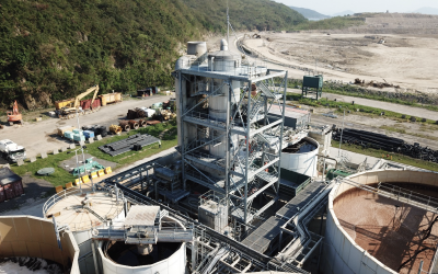
This wasn’t a greenfield design exercise — it was a retrofit onto a working landfill, and that constraint shows up directly in the equipment layout. The obvious way to place a precipitation stage (where the stripped ammonia is captured before oxidation) is at ground level, ahead of the stripper column, where it’s easiest to access and maintain. Here, it’s stacked on top of the stripper instead — because ground-level space at NENT simply wasn’t available for a separate structure. The precipitation section, the stripping column, and a cooling section were combined into one vertical unit roughly 24 metres tall.
That decision has a real trade-off: a taller, single structure is more complex to access for maintenance than a ground-level precipitation vessel would have been, and it demands more careful structural and lifting design. The upside is a materially smaller footprint — the whole thermal/stripping process fits into one column rather than a spread of separate vessels, which matters when you’re threading a new process line into space between two lines already in service.
The same logic drove the commercial scope: rather than a turnkey civils-and-installation contract, the deal was structured as equipment supply plus installation supervision, with the actual civil, mechanical, and electrical installation work carried out by others. Pre-packaging the process into discrete modular skids — built and tested before shipping — was the trade made to keep on-site construction time down, at the cost of needing a separate, coordinated installation contractor.
The Design Envelope
Parameter
Value
Liquid flow rate
1,500 m³/day
Influent ammonia (NH4) concentration
5,500 mg/l
Effluent ammonia (NH4) concentration
<150 mg/l
Ambient temperature, cold conditions
10°C
Relative humidity, cold conditions
35%
Ambient temperature, hot conditions
35°C
Relative humidity, hot conditions
90%
Designing to both ends of that temperature and humidity range (10°C/35% RH through to 35°C/90% RH) means the stripping performance has to hold up across Hong Kong’s full seasonal swing, not just under nominal test-bench conditions.
How the Process Actually Works
The system is built around two core units — one ammonia stripper and one thermal destructor (thermal oxidiser) — connected in a loop that recycles its own heat:
Leachate is pumped in through a leachate heater, which draws its heat from the thermal destructor’s exhaust gas via an economiser — the plant heats its own feed using waste heat from burning off the ammonia it just stripped.
Heated leachate enters the top of the precipitation section, which sits above the stripper column as part of the combined 24m structure.
Leachate then passes down through the stripping section (roughly 13m of the column’s height), where ammonia transfers from the liquid into a counter-current air stream.
At the base, the stripped leachate passes through a cooling section (roughly 6m of column height) to bring its temperature down before discharge.
Stripper air is drawn from atmosphere and routed through that same cooling section before entering the stripper — recovering heat from the outgoing leachate to pre-warm the incoming air. Steam is injected after the cooling section to bring the air to the correct operating condition.
Ammoniated air leaving the top of the stripper is fed directly into the thermal oxidiser as combustion air — the ammonia becomes part of the fuel/air mix rather than a separate waste stream to dispose of.
Exhaust from the thermal oxidiser returns to the economiser, closing the loop by reheating the incoming leachate.
The stripper column itself is built in 254 SMO stainless steel (or equivalent) to handle the corrosive, high-ammonia leachate, with packing running the full height to maximise gas-liquid contact.
Running Costs
Per the design basis, the unit is expected to draw approximately 250 kW of electricity and 6–8 m³/hour of water. Because landfill gas is used as the process-heat and ammonia-destruction fuel, ongoing chemical consumption is limited to anti-foam agent and a relatively small amount of salt for the demineralisation system — there’s no ongoing dosing chemical for the ammonia treatment itself. That efficiency has a fuel-supply dependency built into it: treating this leachate flow needs a minimum landfill gas supply of 2,800–3,200 Nm³/h at 40% methane, meaning the plant’s performance is tied to the landfill continuing to generate gas at that rate and quality — not a given at every site, or at every stage of a landfill’s life.
What’s In the Deal — and What Isn’t
The supply covers a set of discrete, pre-packaged modules: the ammonia stripper column, waste heat economiser (built from seven interchangeable cassettes for easier cleaning), a steam generator, the leachate feed heater, plate-type exit heat recovery, a condenser heat recovery system, feed water treatment (an 80%-efficiency deaerator plus a duplex demineraliser), the thermal destructor, and the associated control panel, HMI/PLC, and instrumentation.
What’s excluded is a longer and arguably more consequential list: inlet and outlet buffer storage, solids removal equipment (relevant if the feedstock runs high in solids), delivery from port to site and offloading, anchor bolts and foundation bolting, all concrete and civil works, any buildings to house the equipment, electrical connection and protection, SCADA/telemetry connectivity, servicing arrangements, interconnecting piping, the electrical supply itself, condensate drainage, civils design, local taxes and import duties, and all mechanical and electrical installation labour. A site office for the installation team during construction is also excluded from supply. In practice, this is an equipment-and-supervision contract, not a turnkey build — a buyer needs their own civils, M&E, and balance-of-plant contractor lined up before this piece can be installed.
Timeline — and Where It Actually Slips
The quoted programme runs 54 working weeks: 8 weeks of design, 32 weeks of procurement and fabrication, 10 weeks of on-site installation (carried out by others, not this contract), and 4 weeks of commissioning and performance testing. Two caveats sit outside that number and matter more than they might first appear: the 54 weeks are working weeks with no allowance for holiday shutdowns, and the programme excludes any time for third-party regulatory approvals — which is explicitly flagged as something that needs adding into a final project schedule separately. On a project like this, the gap between the quoted 54 weeks and the real calendar-time-to-completion is likely to come from exactly those two line items.
Precedent: Built to Match What’s Already Running
This isn’t unproven technology being trialled for the first time — it’s the third stripping line at a site that already operates two. That continuity shows up in a specific engineering detail: the economiser cassette is designed to the same footprint as the cassette used in the existing NENT 2 installation, making it interchangeable and giving the site commonality of spares across its ammonia stripping fleet. For an operator running multiple lines, that’s a meaningful reduction in spares inventory and maintenance complexity, not just a footnote.
The Honest Takeaway
A pre-packaged, modular ammonia stripping plant like this is a strong fit when the constraint is space and construction disruption on a live site, and when a genuinely low-chemical-consumption process is the priority — the landfill-gas-fired heat recovery loop does real work in avoiding a chemical dosing regime. It’s a weaker fit for a buyer expecting a single turnkey contract: civils, M&E installation, and regulatory approvals sit outside this scope and need to be actively managed alongside it, and the whole heat-and-fuel balance depends on a landfill gas supply holding at 2,800–3,200 Nm³/h. Any buyer evaluating a similar package should treat the equipment price as one line in a larger project budget, not the whole of it.
Note: Commercial pricing and payment terms from the source proposal have been intentionally excluded from this piece and are available on request.
Need an ammonia stripping plant?
Organics has designed thermal ammonia stripping systems since 1997
Introduction Organics Ltd, with its head office located in the industrial West Midlands of England, has its origins in the UK landfill gas and leachate industry. Organics now provides a comprehensive, industrially based manufacturing service, with offices, fabrication...
Every wastewater treatment plant spends money getting rid of ammonia. At Severn Trent Water alone, aeration to oxidise ammonia to nitrate costs around £1 million a year, burning through 10 GWh of electricity and generating roughly 5,000 tonnes of CO2 in the process....
Ammonia production accounts for between 3% and 5% of the world's natural gas production. This consumption equates to between 1% and 2% of the world’s energy supply. Here on earth, it requires a great deal of effort to produce ammonia. The following article,...
A new palm oil mill in Kutai Timur, East Kalimantan, is processing 60 tonnes of fresh fruit bunches an hour and with them, up to 600 cubic metres a day of palm oil mill effluent (POME) carrying a chemical oxygen demand (COD) of roughly 100,000 g/m³. That's an enormous...
The problem SBI Group runs a landfill site in Victoria, Australia, and needed to deal with residual odour from its landfill gas stream. The gas doesn't arrive clean: it's a lean, wet mixture — 25% to 50% methane by volume, saturated with moisture, carrying 0% to 5%...