
The works formed part of a landfill restoration at a site where leachate and landfill gas required treatment. Organics supplied the ammonia-stripping plant, the thermal destructor, the enclosed flare and the heat-transfer skids.
Seeing the layout as four streams helps you judge where the heat comes from and where it goes. Leachate would enter from storage, pick up heat, shed ammonia in the packed tower and leave as treated effluent. Stripped ammonia-laden gas would leave the tower top. The destructor exhaust would lose heat to the economiser before venting. When the leachate plant stopped, landfill gas that would otherwise back up was to be routed to the enclosed flare instead of the destructor.
The master panel coordinates to keep the biological stage and the heat stage in step. This integration matters because a thermal ammonia stripping system only makes sense if the upstream and downstream volumes match.
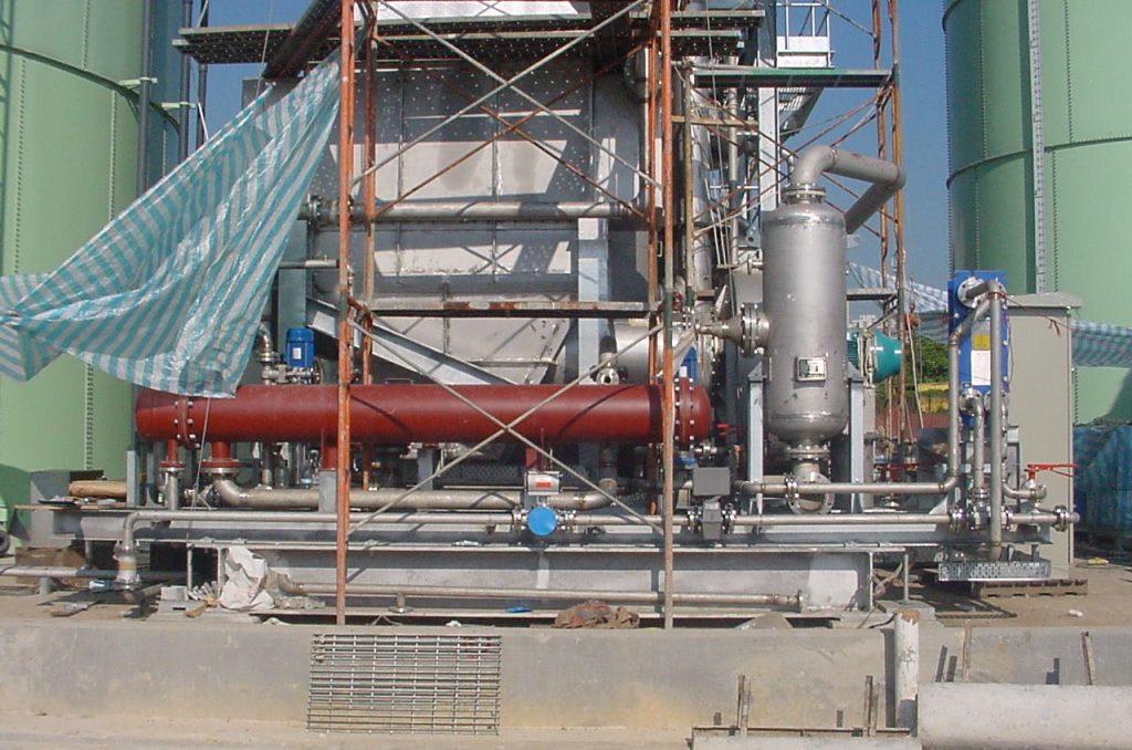
Heat recovery through the economiser and pre-heaters
Leachate arriving at the heat-transfer train would first pass through an inlet plate exchanger. This unit would recover heat from treated leachate leaving the system, prewarming the incoming stream against the outgoing flow. Next, a stripper pre-heater would raise the leachate further against hot water. A flash-pot pre-heater, a vessel where preheated liquid is flashed to steam, would bring the stream up toward stripping temperature. On the exhaust side, an economiser sized for the thermal destructor duty would recharge the same hot-water loop. The circuit was designed to keep water pressurised so it remained liquid while carrying heat from the exhaust stack across to the leachate train.
The economiser sat on the destructor exhaust stack. By cooling exhaust gas, it recovered energy that would otherwise be lost to atmosphere. The hot-water loop then carried that energy across to the leachate side without mixing the two fluids. Using water as an intermediate fluid is a practical choice on a landfill. It lets you pipe the heat source and the corrosive leachate stream independently while buffering temperature spikes from the combustion unit.
The Stripping Tower
The packed tower was specified as a vertical, cylindrical, counter-current random-packed column, 2.35 metres in diameter and 17.8 metres high from the base of the skid, with 15 metres of packing. The packing was 1.25 inch Pall rings. The shell was Avesta Alloy 256 SMO. Normal operating temperature was 69°C, with a minimum of 8°C and a maximum of 96°C. Liquid flow was 9,990 kg/hr. Air flow 7,500 kg/hr.
The 69°C normal temperature was the target the pre-heaters were designed to hit. Air flow at up to 9,990 kg/hr provided the stripping medium, while the cooling tower underneath controlled the exotherm.
Enclosed Flare for Excess Gas
The enclosed flare was specified as a ground flare for landfill gas extracted at the site: 35 percent methane, 12.75 MJ/m³, capacity 3,000 m³/hr. Running hours would follow gas generation, from 0 to 24 hours a day. The stack was 20 metres high and circular, with a 4 metre outlet diameter and 3.8 metre inner diameter for gas flow, built in 304 stainless steel with a 150 mm ceramic-blanket refractory. 48 naturally aspirated burner cups with low-velocity mixers were designed for a chamber temperature of about 975°C. Exhaust temperature was specified in the range 750°C to 1150°C. Ammonia destruction efficiency was 99.5 percent. Retention time was 0.6 seconds at 825°C. Landfill gas would be supplied at a constant rate through a manual control valve. Protection included a low-gas-pressure switch, UV flame-failure detection, low temperature shutdown and high temperature shutdown.
The 150 mm ceramic-blanket refractory inside the 304 stainless steel shell insulated the stack while keeping outer surface temperatures manageable for personnel and equipment nearby. The flare was intended to treat all of the landfill gas when the leachate plant was not in operation.
Site Assembly
The facility master skid was specified at 7.0 m by 15.0 m by 0.45 m and about 18,000 kg. The flare would arrive as a base unit on a skid measuring 3.4 m by 3.4 m by 0.4 m and 320 kg, plus chimney sub-assemblies. Chimney joints would use 58 M20 bolts. Stripper sections would use 48 M20 bolts and an internal weld for a watertight joint, tested with a high-pressure water jet. Skids were to be set to +/- 8 mm with a theodolite. Spreader bars were required on the lifts. Organics planned to supply a specialist erector for the ceramic-blanket lagging.
Setting skids to +/-8 mm with a theodolite may seem like fine tolerances for a landfill, but it ensures the packed tower stays plumb and the bolted chimney joints do not bind during thermal cycling.
Key Takeaways
- A thermal ammonia stripping system can use destructor exhaust to preheat leachate through a closed hot-water loop.
- The design paired a packed tower with an economiser, flash-pot pre-heater and stripper pre-heater.
- An enclosed flare was specified to burn landfill gas independently when the leachate plant was idle.
It comes from the thermal destructor burning stripped ammonia. Exhaust gas passes through an economiser that heats a pressurised hot-water loop. That same water circuit runs through pre-heaters to raise incoming leachate to stripping temperature before it enters the packed tower. The heat is recovered and reused; no extra fuel is needed for preheating.
Leachate enters the packed tower at a normal operating temperature. It arrives at the heat-transfer train and is first raised by recovering heat from treated leachate leaving the system. The stripper pre-heater then lifts it against hot water before it reaches the tower.
A separate enclosed ground flare burns all landfill gas when the leachate plant is idle. It has its own stand-alone control panel and does not form part of the leachate treatment process. The flare runs from 0 to 24 hours a day depending on gas generation and treats both core and migration gas through its own manifold. That keeps the gas path independent of the stripping line.